What Are the Top Types of Electronic Boards in 2026?
As 2026 approaches, electronic board choices are shaped by available space, heat, signal speed, and production volume. The board type alone rarely determines whether a design will succeed. Details matter. A compact wearable and an industrial controller may need very different solutions, even when both use advanced components.
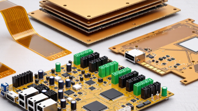
This guide compares common electronic board types, including rigid, flexible, rigid-flex, multilayer, high-density interconnect (HDI), metal-core, and ceramic boards. Each has practical strengths and limits. Rigid boards suit many stable, cost-conscious designs. Flexible boards can fit curved spaces, while rigid-flex combines bendable sections with firmer areas. HDI designs support dense component layouts, but their finer features can demand tighter manufacturing control. Metal-core and ceramic boards may help manage heat or meet specific electrical requirements, though neither is automatically the right choice.
The best option depends on measurable needs: operating temperature, bending cycles, layer count, current, signal integrity, assembly method, and expected production volume. A sample board, design review, and discussion with a qualified manufacturer can uncover problems before full production. Trade-offs can be easy to miss. For instance, reducing board size may complicate repairs or increase fabrication demands. And forecasts about 2026 technology are not guarantees; availability and performance vary by supplier and application. The sections ahead offer a practical way to compare board types and identify the questions worth asking before choosing one.
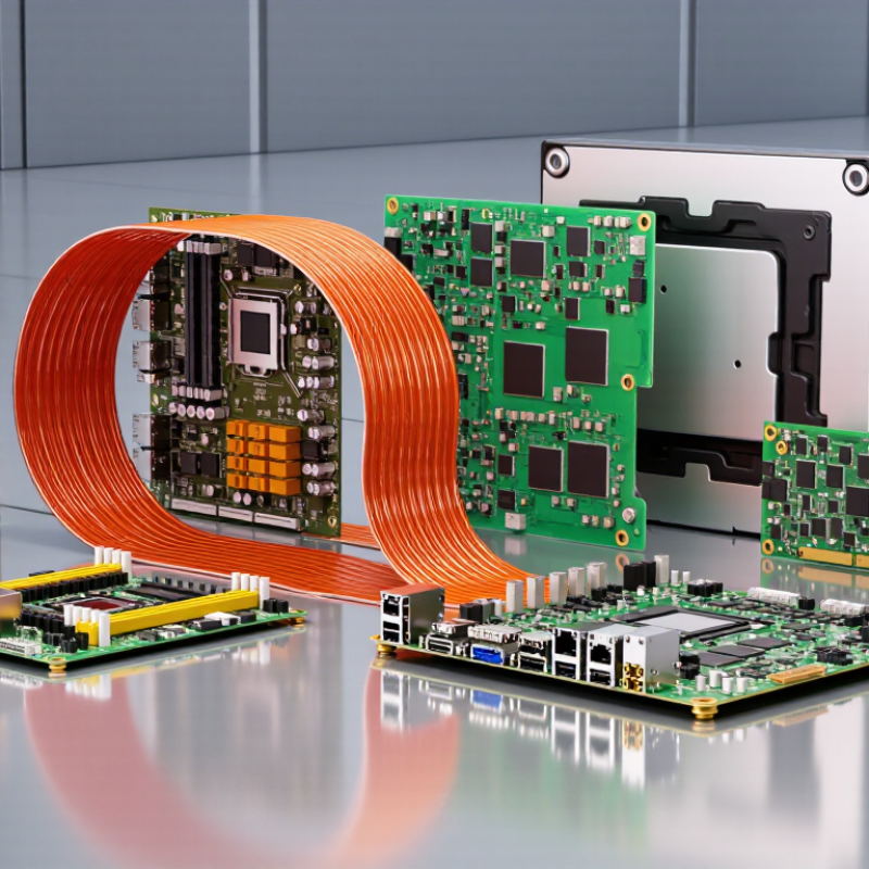
What Electronic Boards Are and How They Function
An electronic board is the physical platform that connects and supports parts in a device.
It may carry a processor, memory, sensors, connectors, and tiny passive components. Copper traces form pathways between them, much like carefully routed streets. Power and signals travel along these paths, while the board’s layers help keep connections compact and organized. The board does not “think” by itself. Its components perform specific jobs, and their layout determines how they work together.
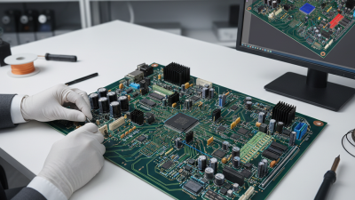
Small details matter. A board in a temperature sensor, for example, can receive a weak signal, filter electrical noise, and send a readable value to another system. Power boards manage energy delivery; communication boards route data between devices. Rigid boards suit many fixed products, while flexible boards can bend around tight spaces. Some designs combine rigid and flexible sections. The right choice depends on heat, vibration, space, power needs, and production requirements—not just the device’s size. Engineers inspect trace spacing, solder joints, and connector placement because a small flaw can cause intermittent faults. Even a well-designed board has limits. Heat can shorten component life, and a loose connector may be hard to diagnose. That part is easy to underestimate.
How Electronic Boards Are Classified by Structure and Materials
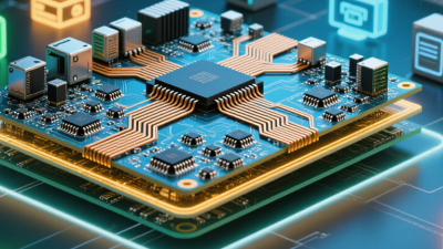
Electronic boards are commonly classified by layer structure and substrate material. These choices affect routing space, stiffness, heat flow, and assembly. Single-sided boards carry copper on one face, while double-sided boards use both faces. Multilayer boards stack copper layers separated by insulating material. They can fit dense connections into a compact footprint.
Rigid boards, usually made with glass-reinforced epoxy such as FR-4, suit fixed installations. Flex boards often use polyimide, allowing circuits to bend around a hinge or narrow enclosure. The bend radius matters: forcing a tight fold can damage copper traces. Rigid-flex boards combine stable mounting areas with flexible sections. Useful, but not automatically better.
Material choice should match operating conditions. Ceramic substrates can provide electrical insulation and good heat transfer, while metal-core boards help move heat away from components. Designers also consider board thickness, moisture exposure, and soldering temperatures. A material label alone tells little about the finished board’s reliability; stack-up details and manufacturing quality matter too. I would not choose by category alone.
The Main Types of Electronic Boards Used in 2026
Electronic boards are not one-size-fits-all; their structure depends on space, heat, motion, and electrical demands. Rigid printed circuit boards remain common in control units, appliances, and computing equipment. Their layered construction supports stable component placement and predictable routing. Reliable workhorses.
Flexible boards use thin polymer films to fit narrow spaces or bend during assembly. They appear in camera modules, wearable devices, and compact displays. Repeated movement still requires careful bend-radius design; flexibility does not make a board indestructible. Rigid-flex boards combine flexible sections with rigid areas, reducing connectors in devices that fold or have irregular shapes. High-density interconnect boards use finer traces and smaller vias, helping designers fit more connections into limited space. More compact, sometimes harder to inspect.
Thermal needs also shape board selection. Metal-core boards transfer heat away from high-power LEDs and similar components, while ceramic boards can suit applications requiring strong thermal stability or electrical insulation. Each option brings manufacturing and cost trade-offs. A useful review checks operating temperature, layer count, bend cycles, and repair needs before layout begins. Specifications alone can miss real assembly constraints, so prototype testing remains valuable.
How Board Types Differ in Performance and Applications
In 2026, the best electronic board depends on the product’s space, heat, and reliability needs. Rigid printed circuit boards suit appliances, control units, and many everyday devices. They provide stable mounting for components and are often economical for established designs. Flexible boards bend around tight spaces, making them useful in wearables, cameras, and moving assemblies. Rigid-flex boards combine both forms. They can reduce connectors, but their design and fabrication usually require more care. Small does not always mean simple.
High-density interconnect boards use finer traces and closely spaced connections. They help compact devices fit more circuitry, though tighter layouts can make heat management and inspection more demanding. Metal-core boards move heat away from components more effectively than many standard boards. That makes them suitable for bright lighting and power electronics, where hot spots can shorten component life. Actual performance depends on materials, copper thickness, airflow, and assembly quality—not the board label alone. A design review can still miss an awkward repair point.
Tips: Match the board type to the real operating conditions. Check available space, bending frequency, expected heat, and repair needs before selecting a design. Ask for thermal and mechanical testing where failure would be costly. A clever layout is not automatically a durable one.
Key Factors for Choosing the Right Electronic Board
Choosing an electronic board starts with its job, not its label. A rigid printed circuit board suits fixed layouts in appliances and control units. Flexible boards bend around tight spaces, such as inside a compact sensor. Rigid-flex designs combine both, but their transitions need careful mechanical review. High-frequency boards may require materials with stable signal properties. Metal-core boards can help move heat away from power components. These types are not interchangeable.
Check the operating environment before settling on a design. A board near a warm motor needs a realistic thermal review, while a handheld device may need low weight and repeated-bend testing. Confirm voltage, current, signal speed, connector locations, and available space. Then consider layer count, material, assembly method, and repair access. A small prototype can reveal awkward cable routing or a connector that is hard to reach. Details matter.
It is easy to over-specify a board because extra layers feel safer. They also add cost and can complicate manufacturing. Ask the design team for test results that match the intended conditions, such as temperature cycling or signal checks. I would not treat one successful prototype as proof of long-term reliability; production variation still needs attention.